5 ประโยชน์ของการใช้รถโฟล์คลิฟท์
รถโฟล์คลิฟท์ (Forklift) เป็นเครื่องจักรอเนกประสงค์ที่สามารถใช้เพื่อประหยัดเวลาและเงินได้เป็นอย่างดี ต่อไปนี้เป็นวิธีการทั่วไป 5… Read More »5 ประโยชน์ของการใช้รถโฟล์คลิฟท์
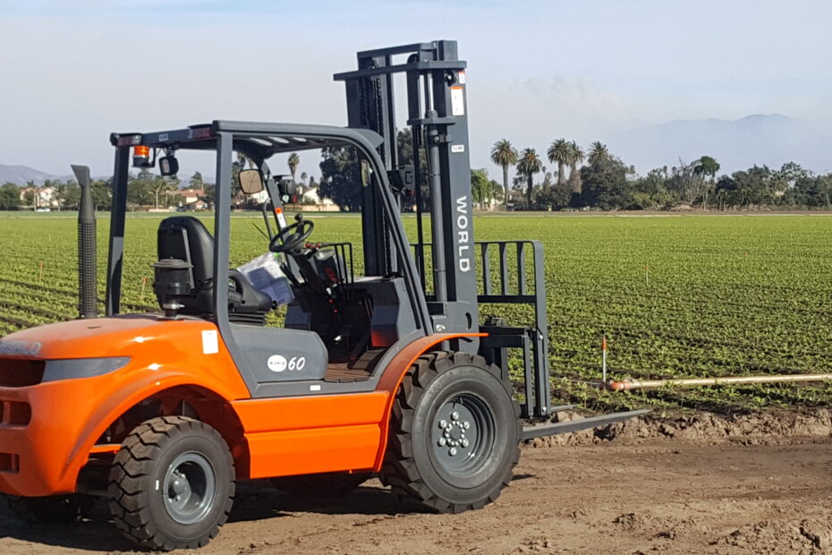
รถโฟล์คลิฟท์ (Forklift) เป็นเครื่องจักรอเนกประสงค์ที่สามารถใช้เพื่อประหยัดเวลาและเงินได้เป็นอย่างดี ต่อไปนี้เป็นวิธีการทั่วไป 5… Read More »5 ประโยชน์ของการใช้รถโฟล์คลิฟท์